To manually configure a tracking avoidance zone, follow these steps.
Important! |
KVH actively monitors your antenna system’s performance and will configure a tracking avoidance zone over the air whenever an obvious blockage area is identified. Therefore, setting up zones yourself on the vessel is unnecessary in most cases. |
Identify the necessary azimuth range for the zone (see Identify the Azimuth Range).
Identify the necessary elevation range for the zone (see Identify the Elevation Range).
At the TracPhone V11-HTS web interface, configure a tracking avoidance zone for that combination of azimuth and elevation ranges (see Configure the Tracking Avoidance Zone(s) at the Web Interface).
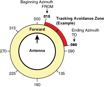
First, you need to determine the necessary azimuth range for the tracking avoidance zone(s). You will need to enter, in clockwise order, the beginning and ending azimuths that define the outer boundaries of the zone, relative to the antenna’s forward arrow, which should be pointing toward the bow.
NOTE: Each tracking avoidance zone must span at least 5º. Therefore, be sure to set beginning and ending azimuths at least 5º apart.
Beginning and Ending Azimuths Defining a Zone (Example)
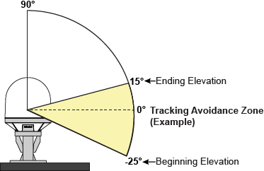
Now you need to determine the necessary elevation range for the tracking avoidance zone(s). You will need to enter, in ascending order, the beginning and ending elevations that define the outer boundaries of the zone.
NOTE: Each tracking avoidance zone must span at least 5º. Therefore, be sure to set beginning and ending elevations at least 5º apart.
Beginning and Ending Elevations Defining a Zone (Example)
At the TracPhone V11-HTS web interface, click the Settings tab. Then click Tracking Avoidance Zones.
Click Edit.
If the Login window appears, log in with the Administrator password.
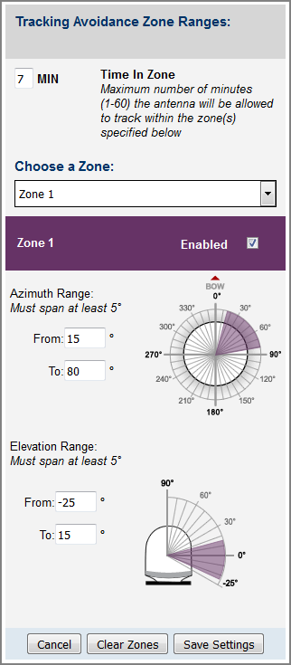
Enter the azimuth and elevation ranges for Zone 1. Then select the Enabled check box.
If you wish to set up another tracking avoidance zone, select a zone from the drop-down menu and repeat step 4 for the selected zone.
In the Time in Zone box, enter the maximum number of minutes (between 1 and 60) during which the antenna will be allowed to track within a tracking avoidance zone (see Tracking Avoidance Zones Overview for details).
Click Save Settings.
At the confirmation message, click Save.
Configuring Tracking Avoidance Zones
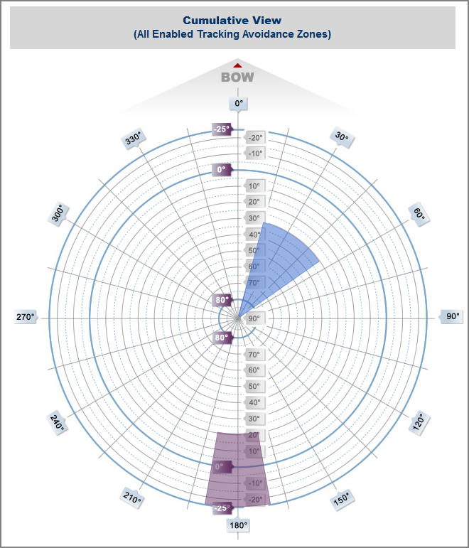
The Tracking Avoidance Zones page displays a diagram that indicates the cumulative azimuth and elevation ranges of the tracking avoidance zones that are currently enabled. The circumference of the circle indicates azimuth, while the radius indicates elevation. In the example shown here, the following tracking avoidance zones are enabled:
Zone 1 (purple) = Azimuth: 170º to 190º, Elevation: -25º to 20º
Zone 2 (blue) = Azimuth: 15º to 55º, Elevation: 30º to 90º
Cumulative View of All Enabled Tracking Avoidance Zones