Status Information
On the system's web interface, you can view status information on the Home and Support pages.
Home Page of the Web Interface
The Home page provides basic system status information.
WAN Connection
Each WAN connection tab includes an icon indicating its general status (identical to the icons on the BDU Touchscreen):
Each WAN connection tab includes an icon indicating its general status:
| State | Connection Status | ||
| VSAT | Cell | Wi-Fi | |
| Currently in use | |||
| Available, but not currently in use | |||
| Not available; disconnected, deactivated, or no Internet access | |||
Note: By default, the system automatically switches to the best available WAN connection. You can also manually switch. See WAN Selection.
The following additional icons apply if you have an optional external gateway connected to the system for use as an alternate or backup connection:
| State | Connection Status | |
| Alternate | Backup | |
| Currently in use | ||
| Available, but not currently in use | ||
| Not available; disconnected, deactivated, or no Internet access | ||
Note: By default, the system will automatically use the alternate WAN connection whenever it is available and will use the backup WAN connection only when no other WAN connections are available. You can also manually switch. See WAN Selection.
VSAT
| Message | Description |
|
Service Status |
General status of the VSAT WAN connection:
|
| SNR | Quality of the received satellite signal; SNR = Ratio of signal level to background noise in decibels |
|
No-Transmit Zones |
Status of the no-transmit zones:
|
|
Antenna |
General status of the antenna:
|
|
Satellite |
Satellite name and orbital slot (longitude) that the VSAT modem has currently selected for tracking |
|
Beam |
Beam of the tracked satellite that the antenna is currently using |
CELL
| Message | Description |
|
Service Status |
General status of the cellular WAN connection (more solid blue bars = better connection):
|
|
Carrier |
Carrier providing the cellular network connection |
|
Service |
Generation of cellular technology in use by the current cellular network:
|
|
SIM Card |
SIM card currently in use for cellular service; also indicates its current status:
|
WI-FI
| Message | Description |
|
Service Status |
General status of the shore Wi-Fi WAN connection (more solid blue bars = better connection):
|
|
SSID |
SSID (network name) of the currently selected shore Wi-Fi network |
|
Security |
Security mode of the currently selected shore Wi-Fi network:
|
ALTERNATE
| Message | Description |
|
Alternate - Port 4 |
General status of the alternate WAN connection (if connected to the designated port):
|
BACKUP
| Message | Description |
|
Backup - Port 3 |
General status of the backup WAN connection (if connected to the designated port):
|
Phone Line
| Message | Description |
| Voice Status | General status of the system’s connection to the VSAT enhanced voice service:
|
| Line 1 | General status of the phone line:
|
| Line 2 | General status of the second phone line, if enabled |
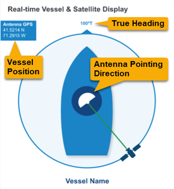
Real-time Vessel & Satellite Display
The Home page also displays the vessel’s GPS position and true heading and provides a graphical representation of the antenna’s pointing direction relative to the bow of the vessel.
IMPORTANT! If true heading is not displayed (shows "No Heading Available" instead), the antenna system does not have a valid connection to the vessel’s NMEA device.
Messages
The Messages block displays any important announcements from the Network Operations Center, such as notifications of service outages. It will also display any active error or warning messages (see Error and Warning Messages).
Support Page of the Web Interface
The Support page provides more detailed system VSAT status information.
General Statistics
| Message | Description |
| Management IP | The built-in VSAT modem’s external satellite IP address; its identity on the mini-VSAT BroadbandKVH ONE network |
| Latitude and Longitude | Vessel position reported by the GPS |
| VSAT Modem State | Status of the VSAT modem's network connection:
|
| Last Login | Date/time of the last successful login to the network |
RX Statistics
| Message | Description |
| FL State | State of the forward link; should be “Locked” while the modem is logged in |
| FL Carrier | Current satellite’s forward link modulation, symbol rate (kilo-symbols/sec), and code rate |
| Composite Power | Measure in dBm of raw satellite signal received at the modem; typical range is -30 to -60 dBm |
TX Statistics
| Message | Description |
| RL State | State of the return link:
|
| RL Carrier | Current satellite’s return link modulation, symbol rate (in kilo-symbols/sec), and code rate |
| Power | The instantaneous transmit power in dBm that the modem is using at the moment |
| Initial Power | The transmit power in dBm that the modem uses when starting the network login process |
| Max Power | The maximum power in dBm that the modem will use (calculated and stored in the modem when the P1dB test is performed at the factory) |
Position Backup Source
Note: This section shows the backup position data provided by whichever NMEA source(s) is currently connected to the BDU – NMEA 0183 and/or NMEA 2000.
| Message | Description |
| State | State of the backup GPS:
|
| Latitude and Longitude |
Latitude and longitude reported by the backup GPS, if connected with a valid fix |
Voltage
| Message | Description |
| BDU | Voltage level in VDC at the BDU's Antenna connector (power supplied to the antenna). |
| Antenna | Voltage level in VDC at the antenna's cable connector (power from BDU minus cable loss). |
![]()
Was this topic helpful? Please share your feedback.
© 2024-2025, KVH Industries, Inc., All rights reserved.